1.0 入力:
1.1 電圧
| 最小 | 最大 | ユニット | |
| 入力範囲 | 90 | 264 | Vrms |
| 定格範囲 | 100 | 240 | Vrms |
AC 入力電圧が90 ~ 99Vの場合、出力ワット数は765Wに低下
1.2 周波数
47Hz ~ 63Hz
1.3 電流
12A/100V, 6A/240V
1.4 突入電流
115V/65A(最大), 230V/130A(最大) at 25℃ (cold start)
1.5 電力周波数
20%/50%/100%の負荷時 AC 115V 60Hz and AC 230V 50Hz, 電力効率は少なくとも87%/90%/87%
1.6 スタンバイモード
「スタンバイモード」状態の測定中はメインコンバーターはオフ状態です。
PS_ON =高) + 5Vsbコンバーターが動作しており、スタンバイ入力電力が測定されます。
| 負荷条件 | 効率性 | パワーイン |
| <45mA | - | <0.45W |
| 45mA | >=50% | - |
| 100mA | >=55% | |
| 250mA | >=65% | - |
| 1.0A | >=75% | - |
| *2013 ErP スタンドバイ効率 | ||
1.7 有効力率補正 (PFC):
2.0 出力:
| グループ | 1 | 2 | ||||
| 電圧 | +3.3V | +5V | +12V | -12V | +5VSB | |
| 最大負荷 | 20A | 20A | 70A | 0.3A | 3.0A | |
| 最小負荷 | 0A | 0A | 0A | 0A | 0A | |
| 電圧規制 | ±3% | ±3% | ±3% | ±10% | ±5% | |
| LOAD REGULATION | ±2% | ±2% | ±2% | - | ±3% | |
| リップル & ノイズ (mV) | 40 | 40 | 60 | 60 | 40 | |
| 容量負荷(uF) | 10000 | 10000 | 20000 | 330 | 10000 | |
備考:
1.連続最大総出力は850Wを超過してはいけません。
+12V DC の最大出力電力は70A (840W) を超過してはいけません。
+3.3V および +5V DCの最大出力電力は100Wを超過してはいけません。
2. 最大ピーク合計DC出力電力は935Wを超過してはいけません。
3. ピーク電力および電流負荷は、最低1秒間サポートされる必要があります。
4. +3.3V、+5V、および +12V DC 出力電圧は、レギュレーションを満たすために図1の相互負荷範囲内にある必要があります。
5. 負荷レギュレーションは、80%負荷と100%負荷の間の出力電圧差を測定します。
6. リップルおよびノイズは、図1のクロスローディング範囲の20MHz帯域幅のオシロスコープを使用したリップルとノイズの測定。システム負荷をシミュレートするには、0.1uFのセラミックディスクコンデンサと10uFの電解コンデンサーを使用してコネクターで出力をバイパスする必要があります。非差動タイプのスコープを使用した場合、プローブのアース線の長さは40mm以下にしてください。
2.1 クロスレギュレーション
+ 5Vと+ 3.3Vの組み合わせ負荷と+ 12VDC負荷は、図1に示すクロス負荷の組み合わせに対してセクション2.0で定義された範囲内にとどまる必要があります。
2.2 ホールドアップ時間:16ms(最小)
テスト条件: 100%ロード時 @ AC 入力 115Vもしくは 230V, 47Hz
2.3 負荷過渡応答(ステップ負荷)
ステップ負荷は、全負荷の60%(12V)および30%(3.3Vおよび5V)まで変化しますが、その他の負荷は定格範囲内で一定に保たれます。負荷波形は、立ち上がりおよび立ち下がりの勾配が1.0A/μsecの方形波とし、周波数は50Hz~10kHzとします。DC出力電圧は、ステップ負荷変動中も±5%の変動範囲内に留まります。
2.4 オーバーシュート
電源オンまたは電源オフ時のオーバーシュートは、公称出力電圧の10%未満でなければなりません。
2.5 タイミング、ハウスキーピング、および制御
ローアクティブPS-ON(DC ON / OFF)入力信号が装備されており、インターフェース有効を提供します。もしくは、DC出力のGROUP1を無効にします。この信号は電気的にTTL、OPENとインターフェースします。
コレクターとハードスイッチ
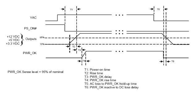
| 信号名 | 最大 | 最小 | ||
| T1 | PS_電源オン時間 | 500mS | ||
| T2 | メイン出力から立ち上がり時間 | 20mS | 0.2mS | |
| T3 | PWR_ok 遅延 | 500mS | 100mS | |
| T4 | PWR_ok 立ち上がり時間 | 10mS | ||
| T5 | PWR_OKホールドアップ時間に対するACロス | 16mS | ||
| T6 | PWR_OK DC損失遅延に対して非アクティブ | 1mS | ||
2.5.1 電源良好信号:
信号タイプ: オープンコレクター +5DC, TTL 互換性
ロジックレベル: <0.4V 4 mA.
ロジックレベル 高: 2.4VDC~ +5V間 出力 調達中 200 uA
最大リッペル/ノイズ: 400mV pk-pk. (非コンデンサーテスト)
3.0 出力保護
3.1 合計電力保護 : (OPP )
シャットダウン時の最大合計電力 150% &ラッチオフ保護
3.2 過電圧保護: (OVP)
| 出力電圧 | 最大電圧 | 結果 | ||
| +3.3V | 4.3V |
シャットダウン & ラッチオフ The Group 1 DC Output |
||
| +5V | 7.0V | |||
| +12V | 15.6V | |||
| +5Vsb | 8.0V | |||
3.3 短絡保護: (SCP)
グループ1の出力間の短絡により、すべてのグループ1がシャットダウンされます。
グループ2での短絡は、グループ1とグループ2共にシャットダウンします。
3.4 非負荷状況: (OCP)
過電流保護は、安全な動作条件下で動作するために電流を制限するように設計されています。+3.3V、+5V、および+12Vレールは、ACラインまたはPS_ONリセットでラッチオフ保護が必要です。+5Vsbレールは、障害状態が除去されると自動的に再起動します。
| Rails | Max. protected current |
| +3.3V | 32A |
| +5V | 32A |
| +12V | 112A |
| +5Vsb | 8A |
3.5 過熱保護: (OTP)
本電源には過熱保護センサーが搭載されており、設定温度に達すると作動して電源をシャットダウンします。このような過熱状態は、通常、冷却ファンの故障または動作温度の上限を超えた場合に発生します。
3.6 無負荷状態
すべてのDC出力コネクターが負荷から切り離されている状態では、損傷や危険な状態は発生しません。電源がシャットダウン状態になる場合があります。
3.7 シャットダウン後リセット
出力のエラー状態が原因で電源装置がシャットダウン状態にラッチされると、エラーが取り除かれます。PS_ON#が再びローに引き下げられた後にのみ、電源ユニットは通常の動作に戻ります。
5Vsbの故障状態により電源がシャットダウン状態になった場合、故障が解消され、電源スイッチ(電源コード)がオフ/オン(プラグアウト/イン)された後にのみ、電源は通常の動作に戻ります。最小オフ時間は3秒です。
4.0 電源ユニットの冷却
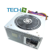
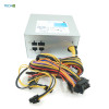
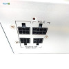
搭載されている冷却ファンはDC出力ケーブル側の通気孔から空気を吸い込み、ACレセプタクル側で排気します。また、本ファンは電源ユニットの内部冷却専用であり、システム冷却用ではございません。
ファンパラメーター:
|
定格電圧 |
12VDC |
|
サイズ |
120*120*25(mm) |
|
エアーフロー |
62.26CFM/分 |
|
ノイズ |
34db(A) |
5.0 環境
5.1 作動
稼働温度: 0 ~ 50℃ (定格電力は40℃~50℃時100%~80%に低下します)
周辺湿度 : 85%まで 相対湿度 (結露なし)
5.2 温度/ストレージ
周囲温度:-40~85℃
相対湿度: 95% 相対湿度 (結露なし)
6.0 MTBF
25℃で100,000以上(DCファンを除く)
7.0 EMC
CE Class B
FCC Class B
8.0 安全性
cTUVus
TUV
CB
CCC
BSMI
RCM
9.0 サイズ
L 140mm x W 150mm x H 86mm, +/-1mm
関連商品
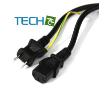
I-SHENG PSE C13 & 2ピン アース コネクター電源コード E1.5M
仕様: 12A – 125V 長さ: 1.5m 材質: PVC 認証: PSE, RoHS オス SP-18C メス IS 14 仕様書1 仕様書2..
¥1,024 税別:¥931


