


1.0 入力:
1.1 電圧
| 最小 | 最大 | ユニット | |
| 入力範囲 | 100 | 264 | Vrms |
| 定格範囲 | 100 | 240 | Vrms |
1.2 周波数
47Hz ~ 63Hz
1.3 電流
8A/100V, 4A/240V
1.4 突入電流
115V/50A (最大), 230V/100A (最大) 25℃時 (コールドスタート)
1.5 電力周波数
20%/50%/100%の負荷時 AC 115V 60Hz and AC 230V 50Hz, 電力効率は少なくとも 82%/85%/82%
1.6 スタンドバイモード
「スタンバイモード」状態の測定中はメインコンバーターはオフ状態です。
(PS_ON =高) + 5Vsbコンバーターが動作しており、スタンバイ入力電力が測定されます。
| 負荷条件 | 効率性 | パワーイン |
| <45mA | - | <0.45W |
| 45mA | >=50% | - |
| 100mA | >=55% | |
| 250mA | >=65% | - |
| 1.0A | >=75% | - |
| *2013 ErP スタンドバイ効率 | ||
1.7 有効力率補正 (PFC):
>0.9 at 50% 負荷時, AC 115v 60Hz
2.0 出力:
| グループ | 1 | 2 | ||||
| 電圧 | +3.3V | +5V | +12V1 | +12V2 | -12V | +5VSB |
| 最大負荷 | 24A | 24A | 20A | 20A | 0.3A | 2.5A |
| 最小負荷 | 0.3A | 0.5A | 0.1A | 0.4A | 0.005A | 0A |
| 電圧規制 | ±5% | ±5% | ±5% | ±5% | ±10% | ±5% |
| リップル & ノイズ (mV) | 50 | 50 | 120 | 120 | 120 | |
| 容量負荷(uF) | 10000 | 10000 | 10000 | 330 | 10000 | |
備考:
1.連続最大総出力電力は500Wを超過してはいけません。
+ 12V DC最大出力電力は38A(456W)を超過してはいけません。
+ 3.3Vおよび+ 5VDCの最大合計出力電力は130Wを超過してはいけません。
2.最大ピーク合計DC出力電力は550Wを超過してはいけません。
最大12秒、1分あたり最大1回の発生(115Vac 60Hz、230Vac 50Hz)。
3.+ 12V1&+ 12V2が38Aで出力される場合、-12Vの出力負荷は最小0.1Aです。
4.24Aで3.3V出力の場合、+ 12V1&+ 12V2の合計出力負荷は最小3Aです。
5.24Aで5V出力の場合、+ 12V1&+ 12V2の合計出力負荷は最小3Aです。
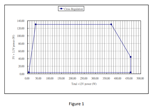
6.+ 3.3V、+ 5V、および+ 12V DC出力電圧は、レギュレーションを満たすために図1の相互負荷範囲内にある必要があります。
7.
図1のクロスローディング範囲の20MHz帯域幅のオシロスコープを使用したリップルとノイズの測定。
システム負荷をシミュレートするには、0.1uFのセラミックディスクコンデンサと10uFの電解コンデンサーを使用してコネクターで出力をバイパスする必要があります。
非差動タイプのスコープを使用した場合、プローブのアース線の長さは40mm以下にしてください。
2.1 クロスレギュレーション
+ 5Vと+ 3.3Vの組み合わせ負荷と+ 12VDC負荷は、図1に示すクロス負荷の組み合わせに対してセクション2.0で定義された範囲内にとどまる必要があります。
2.2 ホールドアップ時間:10ms(最小)
験条件: 100%ロード時 @ AC 入力 115Vもしくは 230V, 47Hz .
2.3 過渡応答のロード(ステップロード)
各出力の出力過渡ステップサイズは、次の表で定義されています。
| 出力 | 出力最大ステップサイズ (定格出力アンペア%) |
出力最大ステップサイズ(A) |
| +12Vdc | 60% | ― |
| +5Vdc | 30% | ― |
| +3.3Vdc | 30% | ― |
定格負荷スルー定格1.0A / uS。出力電圧レギュレーションと容量性負荷は、DC出力テーブルで定義されています
2.4 オーバーシュート
電源オンまたは電源オフ時のオーバーシュートは、公称出力電圧の10%未満でなければなりません。
2.5 タイミング、ハウスキーピング、および制御
ローアクティブPS-ON(DC ON / OFF)入力信号が装備されており、インターフェース有効を提供します。
もしくは、DC出力のGROUP1を無効にします。この信号は電気的にTTL、OPENとインターフェースします。
コレクターとハードスイッチ
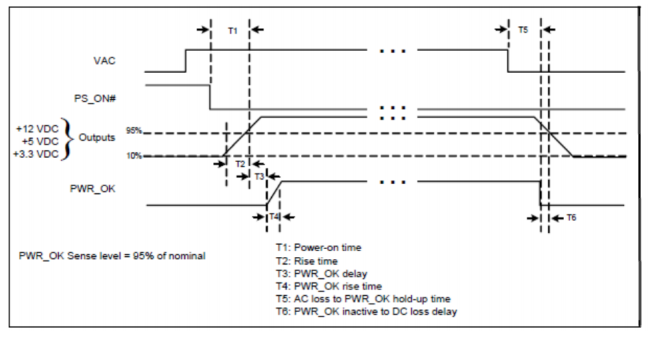
| 信号名 | 最大 | 最小 | ||
| T1 | PS_電源オン時間 | 500mS | ||
| T2 | メイン出力から立ち上がり時間 | 20mS | 0.2mS | |
| T3 | PWR_ok 遅延 | 500mS | 100mS | |
| T4 | PWR_ok 立ち上がり時間 | 10mS | ||
| T5 | PWR_OKホールドアップ時間に対するACロス | 10mS | ||
| T6 | PWR_OK DC損失遅延に対して非アクティブ | 1mS | ||
2.5.1 電源良好信号:
信号タイプ: オープンコレクター +5DC, TTL 互換性
ロジックレベル: <0.4V 4 mA.
ロジックレベル 高: 2.4VDC~ +5V間 出力 調達中 200 uA
最大リッペル/ノイズ: 400mV pk-pk. (非コンデンサーテスト)
3.0 出力保護
3.1 合計電力保護: (OPP )
シャットダウン時の最大合計電力 150% &ラッチオフ保護
3.2 過電圧保護: (OVP)
| 出力電圧 | 最大電圧 | 結果 | ||
| +3.3V | 4.5V | シャットダウン & ラッチオフ | ||
| +5V | 7.0V | |||
| +12V | 15.6V | |||
| +5Vsb | 7.0V | 自動再起動 | ||
3.3 短絡保護: (SCP)
グループ1の出力間の短絡により、すべてのグループ1がシャットダウンされます。
グループ2での短絡は、グループ1とグループ2共にシャットダウンします。
3.4 非負荷状況
すべてのDC出力コネクターで損傷や危険な状態が発生することはありません
負荷から切断されました。電源装置がシャットダウン状態になる場合があります。
3.5 シャットダウン後リセット
出力のエラー状態が原因で電源装置がシャットダウン状態にラッチされると、エラーが取り除かれます。
PS_ON#が再びローに引き下げられた後にのみ、電源ユニットは通常の動作に戻ります。
5Vsbの故障状態により電源がシャットダウン状態になった場合、故障が解消され、電源スイッチ(電源コード)がオフ/オン(プラグアウト/イン)された後にのみ、
電源は通常の動作に戻ります。最小オフ時間は3秒です。
4.0 電源ユニットの冷却
搭載されている冷却ファンはDC出力ケーブル側の通気孔から空気を吸い込み、ACレセプタクル側で排気します。
また、本ファンは電源ユニットの内部冷却専用であり、システム冷却用ではございません。
ファンパラメーター:
| 定格電圧 | 12VDC |
| サイズ | 80*80*15(mm) |
5.0 環境
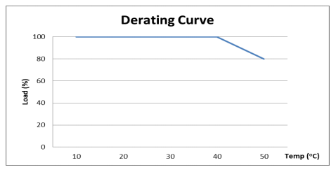
5.1 作動
稼働温度: 0 ~ 50℃
(定格電力は40℃~50℃時100%~80%に低下します)
(結露なし)稼働高度 0 ~ 10,000 フィート
5.2 温度/ストレージ
周囲温度:-40 ~ 85℃
相対湿度: 5 ~ 95% (結露なし)
6.0 MTBF
100,000時間以上 DCファンを除く
7.0 EMC
EN55032:2015+AC: 2016 Class B
EN61000-3-2: 2014 Class A/D
EN61000-3-3: 2013
EN55024: 2010+A1: 2015
FCC Part Subpart 15B
ANSI C63.4-2014
ICES-003 Issue6: 2016
CAN/CSA-CISPR 22-10
AS/NZS CISPR 32: 2015
CISPR 32:2015+C1: 2016
CNS13438 (2006)
GB/T9254-2008
8.0 安全性
IEC 62368-1: 2014
IEC 60950-1(ed.2); am1; am2
UL 62368-1: 2014
CAN/CSA-22.2 No.62368-1: 2014
EN 62368-1: 2014
GB17625.1-2012; GB4943.1-2011
CNS14336-1(2010), CNS15663 (2013)
9.0 サイズ
W 150mm x L 140mm x H 86mm, +/-1mm.
オプション
| 画像 | 商品名 | Model | 価格 | 数量 | 商品購入 |

| I-SHENG PSE C13 & 2ピン アース コネクター電源コード E1.5M | PSE-C13/2P E1.5M |
¥1,024 |
| カートに入れる |

| TA-PSE-C13/2P E2M - PSE 日本 電源コード ケーブル w/グラウンド - ブラック | TA-PSE-C13/2P E2M |
¥888 |
| カートに入れる |
|
| TA-PSE-C13/2P E5M - PSE 日本 電源コード ケーブル w/グラウンド - ブラック | TA-PSE-C13/2P E5M |
¥1,251 |
| カートに入れる |
- アクティブ パワー ファクター補正 [99% PF Typical]
- ユニバーサル AC 入力 [フルレンジ]
- ダブルフォワードコンバータ設計
- Smart & Silent ファン コントロール (S2FC)
- Ample +12V 出力

関連商品

I-SHENG PSE C13 & 2ピン アース コネクター電源コード E1.5M
仕様: 12A – 125V 長さ: 1.5m 材質: PVC 認証: PSE, RoHS オス SP-18C メス IS 14 仕様書1 仕様書2..
¥1,024 税別:¥931

Seasonic SSP-300SFB 電源ユニット
SFB 電源ユニット Seasonic SSP-300SFBはSFX12 V v.2.31に準拠しており、安全な操作ができるように重要な保護機能を提供しています。 ..
¥9,856 税別:¥8,960

CP-465 - 4U XL-ATX シャーシ
型番: CP-465 サイズ(WxHxD): 482 x 177 x 650 mm 梱包サイズ CBF / CBM: 4.8 / 0.4 梱包 N.W / G.W: 12 kg ..
¥33,154 税別:¥30,140

CP-R20-20XX CP-20XX 交換用電源コード
IEC ソケット付き3芯電源コード 10A 125V 長さ:1000mm 重さ:110g CP-2055NおよびCP-2066Nには付属しておりますので、追加..
¥1,056 税別:¥960

Noctua Seasonic PRIME TX-1600 Noctua Edition 電源ユニット
Seasonicは、プレミアムクラスのPC電源ユニットメーカーとして世界的に高い評価を受けています。 PRIME TXシリーズはそのフラッグシップモデルで、80 PLUS® Titanium認証を取..
¥113,300 税別:¥103,000
タグ: Seasonic, SSP-500ES2, パワーサプライ